Become a leader in the IoT community!
Join our community of embedded and IoT practitioners to contribute experience, learn new skills and collaborate with other developers with complementary skillsets.


Join our community of embedded and IoT practitioners to contribute experience, learn new skills and collaborate with other developers with complementary skillsets.


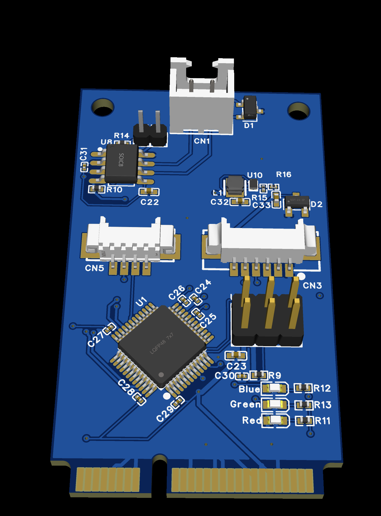
Very new to designing a PCB and want to see how well I’ve done. This is a Mini PCI-e card that is a mixture of the CANable USB module but in a PCI-e form for the development board I’m working with, but I’ve also added connections for a Beitian be-880 GPS module.


SCH_Schematic1_2024-10-19.pdf
I haven’t had a deeper look. I think the schematic might be missing a page for the connector nets of the mPCIe.
Make sure you order the right thickness PCB. I think its 1mm thick for PCIe cards. the usual 1.6mm PCB won’t fit in the connector.
You could rename the LEDs as PWR,STAT and WORD instead of red, blue and green, there is no information, the user can see the color of the led.
I’d also add a lot of test points, its very helpful in debugging. Consider adding them on power nets, and CAN Rx Tx, status signals (sometimes the LEDs could be soldered in reverse by the manufacturer), You can also connected some free GPIO to test points, this can be helpful in debugging firmware, you can flip this GPIO in some function when you need it.
Cheers!
That’s some information that I didn’t know about. I will certainly look into that some more.
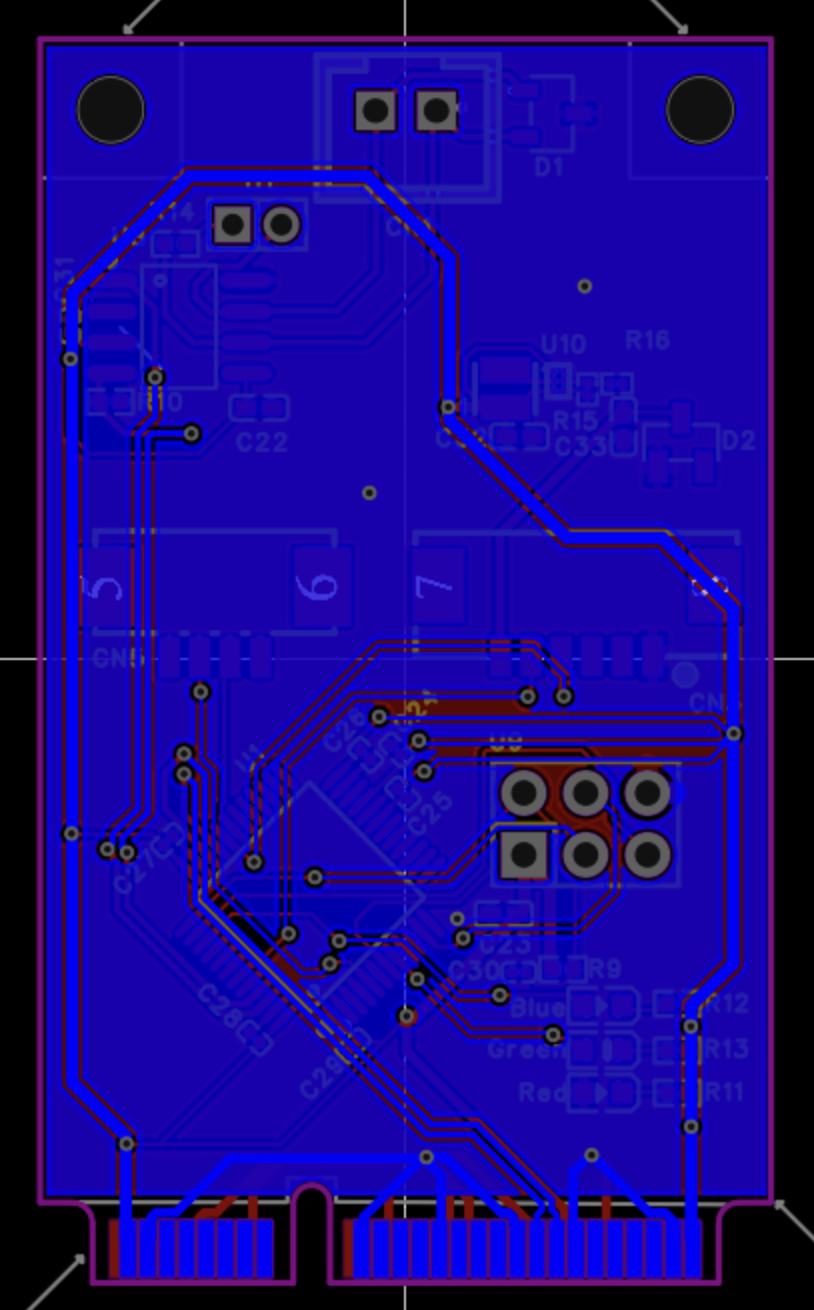
Great design, make sure you use impedance control at the points that is required, and also make sure your traces are are well calculated for current capacity and etc.
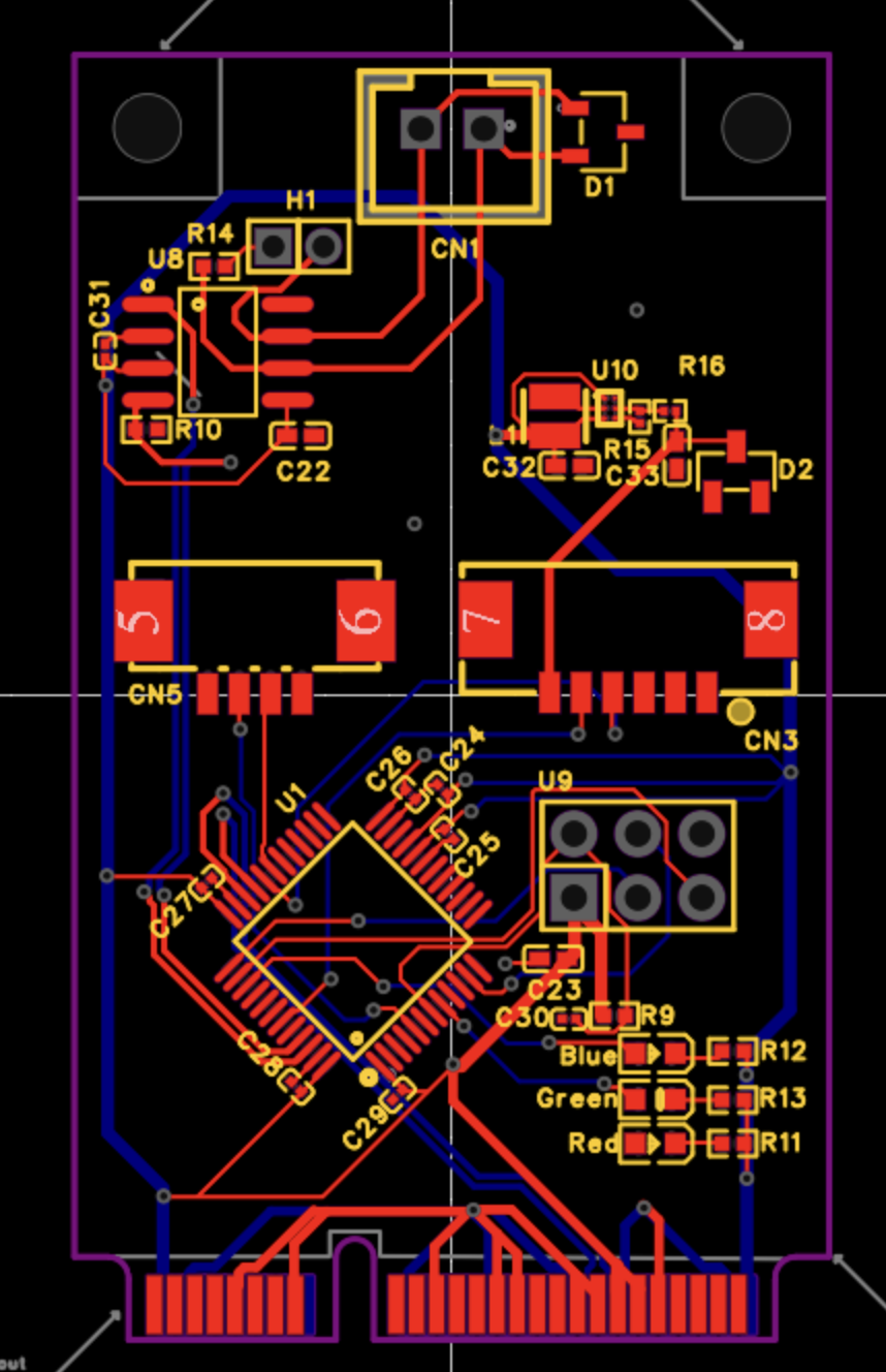
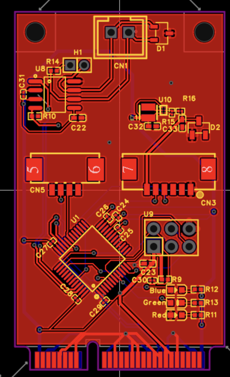
Is this a two layers design
Yes, this is only 2 layers. I did make some changes to it before I sent it for manufacturing.
I’m still learning but what points would require impedance control if you don’t mind teaching a bit.
CONTRIBUTE TO THIS THREAD