Become a leader in the IoT community!

Join our community of embedded and IoT practitioners to contribute experience, learn new skills and collaborate with other developers with complementary skillsets.

Step 1 of 5

CREATE YOUR PROFILE *Required

OR
Step 2 of 5

WHAT BRINGS YOU TO DEVHEADS? *Choose 1 or more

Connect & collaborate 🀝with other tech professionals
Learn & Grow πŸ“š
Contribute Experience & Expertise πŸ”§
Step 3 of 5

WHAT'S YOUR INTEREST OR EXPERTISE? *Choose 1 or more

Hardware Design πŸ’‘
Embedded Software πŸ’»
Edge Networking ⚑
Step 4 of 5

Personalize your profile

Step 5 of 5

Read & agree to our COMMUNITY RULES

  1. We want this server to be a welcoming space! Treat everyone with respect. Absolutely no harassment, witch hunting, sexism, racism, or hate speech will be tolerated.
  2. If you see something against the rules or something that makes you feel unsafe, let staff know by messaging @admin in the "support-tickets" tab in the Live DevChat menu.
  3. No age-restricted, obscene or NSFW content. This includes text, images, or links featuring nudity, sex, hard violence, or other graphically disturbing content.
  4. No spam. This includes DMing fellow members.
  5. You must be over the age of 18 years old to participate in our community.
  6. You agree to our Terms of Service (https://www.devheads.io/terms-of-service/) and Privacy Policy (https://www.devheads.io/privacy-policy)
By clicking "Finish", you have read and agreed to the our Terms of Service and Privacy Policy.

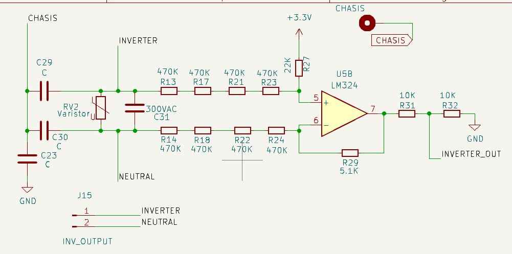
MCU-based Solar Inverter Monitoring System

So I was working on a monitoring system for solar inverters , whereby I can measure the inverter output voltage and current, and also measure the Grid input voltage also, from it I can get the power consumed and also the energy used, to measure the parameters using my MCU, I used differential amp to measure the voltages, the video below is my voltage at my ADC pin, when Grid is available and the inverter is running, I used an offset to ensure the microcontroller captures the positive and negative voltage. S o at 260v the scope VMAX will be around 3.1v. currently my inverter output is 220v. The image attached is the schematic for reading the AC voltage
file1.jpg

  1. jeremycook#0000

    I havent’ watched this whole video: https://www.youtube.com/watch?v=9lEtkysFGGg but in the first 9:00 it shows the massive difference that moving a ground plane closer to your s1 GHz signal can have. Hopefully I can come back to the video, but seems like some good info based on the first bit.

  2. afuevu_#0000

    Thanks for this @jeremycook

CONTRIBUTE TO THIS THREAD

Browse other questions tagged 

Leaderboard

RANKED BY XP

All time
  • 1.
    Avatar
    @Nayel115
    1620 XP
  • 2.
    Avatar
    @UcGee
    650 XP
  • 3.
    Avatar
    @melta101
    600 XP
  • 4.
    Avatar
    @chitour
    600 XP
  • 5.
    Avatar
    @lifegochi
    250 XP
  • 6.
    Avatar
    @Youuce
    180 XP