Become a leader in the IoT community!
Join our community of embedded and IoT practitioners to contribute experience, learn new skills and collaborate with other developers with complementary skillsets.


Join our community of embedded and IoT practitioners to contribute experience, learn new skills and collaborate with other developers with complementary skillsets.


i also re-write the code by changing the order of the operation.
i was not able to test it because i don’t have the hardware, but you can make the test from your side
i used defined macros in stm32f1xx.h and stm32f103xb.h
these files should already be in your project
i think using these defined macros give a more readable code, and will be easier to modify
if you write like this to optimise your code, using defined macros have no impact on the binary size because the macros are processed before compiling : so in both case the compiler receive the same code
here is y code :
void CAN1_Init()
{
// enabling GPIOA clock
SET_BIT(RCC->APB2ENR, RCC_APB2ENR_IOPAEN);
// enabling CAN1 clock
//it is just 1 bit, no need to clear before set
//CLEAR_BIT(RCC->APB1ENR, RCC_APB1ENR_CAN1EN);
SET_BIT(RCC->APB1ENR, RCC_APB1ENR_CAN1EN);
delay_ms(1000);
// enabling AFIOEN clock
SET_BIT(RCC->APB2ENR, RCC_APB2ENR_AFIOEN);
// CAN_RX PA11
//this pin AF or input ?
MODIFY_REG(GPIOA.CRH, GPIO_CRH_MODE11_Msk, 0);
// CAN_TX PA12
MODIFY_REG(GPIOA.CRH, GPIO_CRH_MODE12_Msk, 0xB);
// Enter initialization mode
SET_BIT(CAN1->MCR, CAN_MCR_INRQ);
while ((CAN1->MSR & CAN_MSR_INAK) != 1);
//Exit from sleep mode
CLEAR_BIT(CAN1->MCR, CAN_MCR_SLEEP);
while ((CAN1->MSR & CAN_MSR_SLAK) != 0U);
// TIME TRIGERRED DISABLE
CLEAR_BIT(CAN1->MCR, CAN_MCR_TTCM);
// AUTO BUSS OFF DISABLE
CLEAR_BIT(CAN1->MCR, CAN_MCR_ABOM);
// DISABLE AUTO WAKEUP
CLEAR_BIT(CAN1->MCR, CAN_MCR_AWUM);
// AUTO RETRANSMISSION ENABLED
CLEAR_BIT(CAN1->MCR, CAN_MCR_NART);
// RECEIVED FIFO DISABLED
CLEAR_BIT(CAN1->MCR, CAN_MCR_RFLM);
// PRIORITY DRIVEN BY IDENTIFIER
CLEAR_BIT(CAN1->MCR, CAN_MCR_TXFP);
// ENABLE LOOP BACK MODE
SET_BIT(CAN1->BTR, CAN_BTR_LBKM);
CLEAR_BIT(CAN1->BTR, CAN_BTR_SILM);
WRITE_REG(CAN1->BTR, 0 |
(0 << CAN_BTR_SJW_Pos) | //// SETTING SJW TO 1 (12 << CAN_BTR_TS1_Pos) | // TIMER SEGMENT 1 TO BE DECIMAL 13 (1 << CAN_BTR_TS2_Pos) | // TIMER SEGMENT 2 TO BE DECIMAL 2 (9-1) | CAN_BTR_LBKM); // PRESCALER IS 9, BUT 8 IS SENT for 250kbs CLEAR_BIT(CAN1->MCR, CAN_MCR_INRQ);
while ((CAN1->MSR & CAN_MSR_INAK) != 0U);
}
Hey @m.alarab thanks man, it worked I just tried it, i will observe what you did differently, I appreciate
@m.alarab for some reason this setting the can rx pin as input is the problem.
MODIFY_REG(GPIOA->CRH, GPIO_CRH_MODE11_Msk, 0); this works
GPIOA->CRH &= ~(0x0F << 12); // CAN_TX PA12 GPIOA->CRH |= (8 << 12); this dosent work
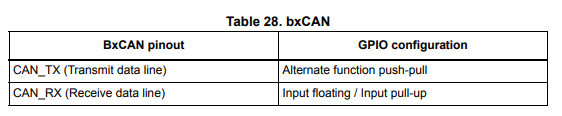
yes it is mentioned in the reference manual, the rx should be set to input.
if you use the MODIFY_REG, i missed to shift the last argument (modify to 0<
Yeahh
So it seems if I set the input to INPUT PULL-UP, it doesn’t work, but when I set it to INPUT FLOATING, it works
Hi @afuevu_
i checked you code,
i notice the pin config of PA11 is not correct, CAN_Rx should be set to input
but i sont know if it resolve your problem
CONTRIBUTE TO THIS THREAD