Become a leader in the IoT community!
Join our community of embedded and IoT practitioners to contribute experience, learn new skills and collaborate with other developers with complementary skillsets.

Join our community of embedded and IoT practitioners to contribute experience, learn new skills and collaborate with other developers with complementary skillsets.


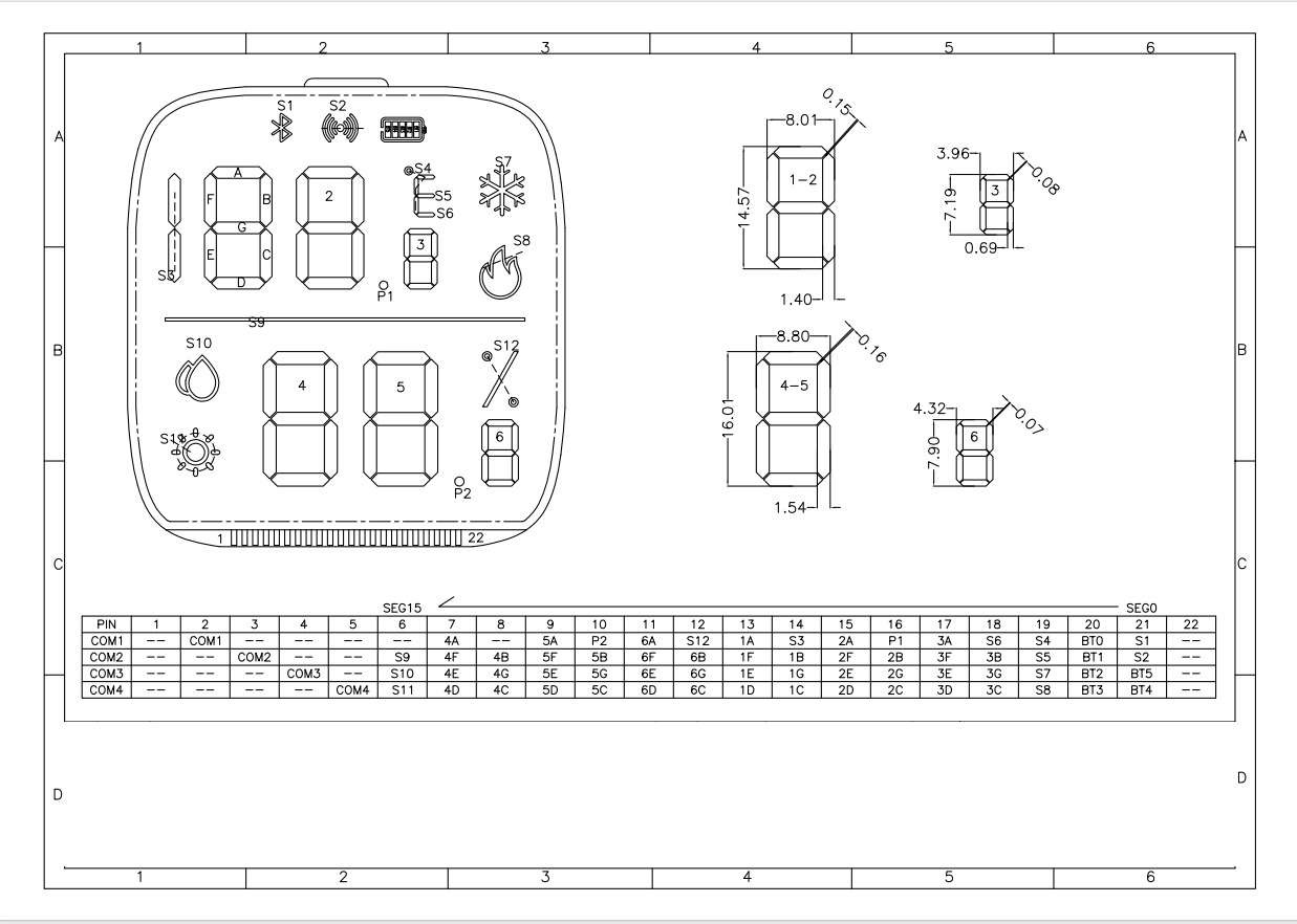
I need to write driver for this
I cannot seem to understand
What does this table means
It is connect to driver ic ht16c21
Which has ram mapping but i have no idea how to let say display 4 on segment number 1


This is a ram layout of the memory. And each address in the memory is a map for glowing the particular led on the display. To glow a particular led on a display you have to write to that memory address.
Oh wait a sec it is a pin diagram of that led (maybe lcd )
Display.
from what i can see from only this sheet
i feels like a pin mapping of (1-22) and common lines(COM1 -COM4)
when you connect these, it activates a certain part on the display
for ex: the blue tooth display is denoted with: S1
which with pin 21 anf COM1,
Ok from what I can interpret is.
You need an ic to drive this led display and
if you don’t have and you are directly connecting each pin to the microcontroller then you have to write the firmware for controlling this led display yourself.
You can think of pins like a matrix.
So if you give power to com1 (pin2) and 4A (pin7).. there is mentioned that 4A , in the diagram you can see written 4 that is seven segments to which it is connected and A means it is connected to the top part segment of that seven segment.
Like this every part of the display is connected.
Like if you want to glow that bluetooth icon you have to power S1.
Go to the table and find the pins. It is connected with pin 21 and com1 which is pin 2. Let’s turn those pins on and your bluetooth icon will glow.
🥲… I didn’t see you had mentioned the driving ic.
Oh!.. I see it is connected to ht16c21 check it datasheet and you can find it communication protocols and the command to write buffer in the ram
It is similar to my last project.
Ig.
If you face any problem you can ask more
@sageboy0918
I did read the datasheet it does have memory map
Com1-4 are columns
Seg0-15 are rows in memory map
In order to control the display i think i have to make some sort of map
Since in picture there is pin layout e.g to turn 1st display and display digit 4 on it i have first put address of seg8 in ram memory and then turn on com2 and 3
Can you share the datasheet?
Sure
Here it is
Read the data sheet from section 5.12
Just giving hints so that you can learn yourself
I assume you are using i2c
It contains information regarding how to send ram buffer
Regarding the size and shape of the buffer read from section 5.2
I hope you know how i2c works.
I know how ic works
I need to know how to make display work with memory map
And make user friendly api
Read datasheets from here
You have to send data in a particular order over i2c so that the driver can interpret it
Yes you are right, good.
But you have to tell the driver what thing you are sending to it.
For telling that there are some commands.
For that you have to read section 5.12
Like you first send 00 which tells the driver you are going to send ram data next
Have you got it?
I got it i need to create map based on seg for each display and com related to that display
E.g seg 8 and 7 control display 1 abcdefg
So i have to make map for it and then do something more
Yes. I haven’t read the whole datasheet you have to figure that out everything by yourself.
But you are on a correct path 👏.
There are more commands inside it , like make a led blink and driver handle it by itself you don’t have to write code for it you just have to send command.
Make sure you read the full datasheet properly and utilizes the display’s full potential.
CONTRIBUTE TO THIS THREAD